[Computer Chassis] AP202 / AP202 ARGB Disassembly and Assembly Instructions
Notice
1. Kindly wear gloves to protect your hands before proceeding with disassembly or assembly. Pay special attention to the corners of the parts to avoid any scratches.
2. When the side panel or front panel is made of glass, please handle it with extreme care during disassembly to avoid any collisions, falls, or undue stress.
3. When disassembling, please lay the casing flat on a stable surface to prevent the side panel from falling during the process.
4. Kindly ensure that the relevant wires are neatly arranged during assembly to prevent any damage to the wires throughout the process.
5. Keep track of all screws and small components during disassembly and assembly to avoid losing any parts.
Preparation
Phillips screwdriver PH2
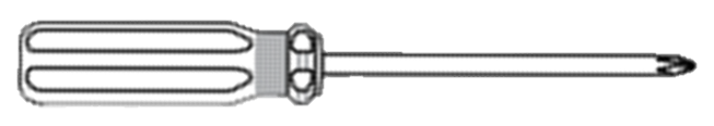
Side Panels
- Left Panel
Turn the two thumbscrews counterclockwise to loosen them, then slide the panel outward.

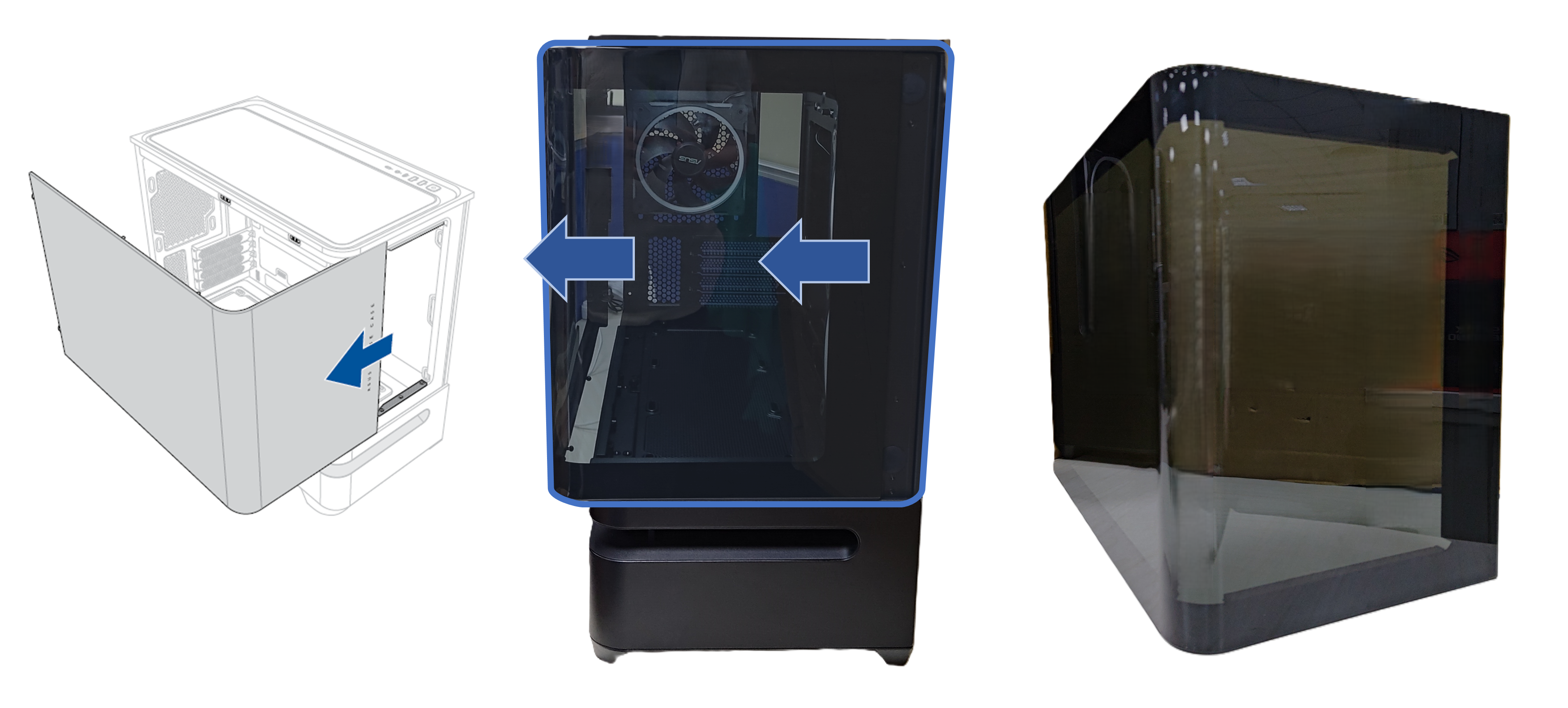
- Right Panel
Gently pull both sides of the panel outward to release it from the clips. Then, detach the top edge and lift off the panel.
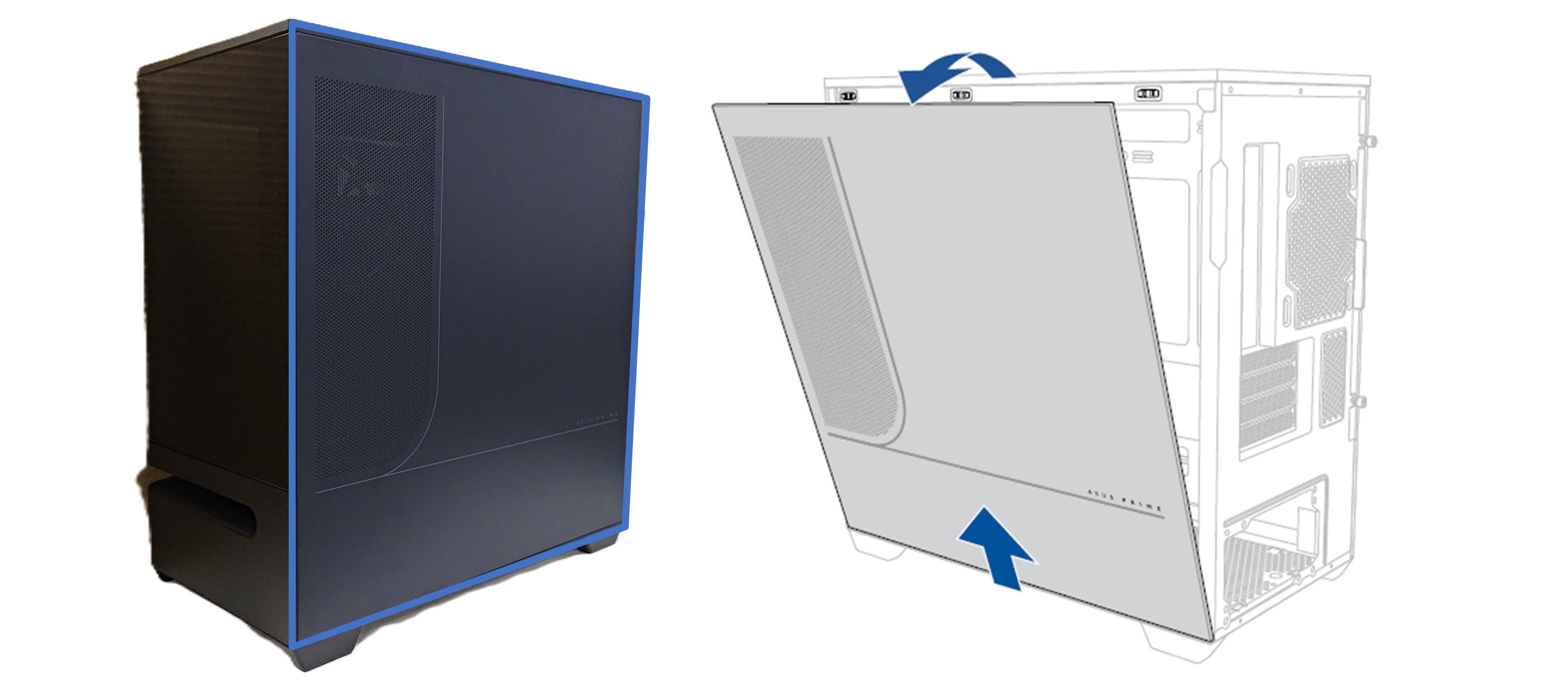
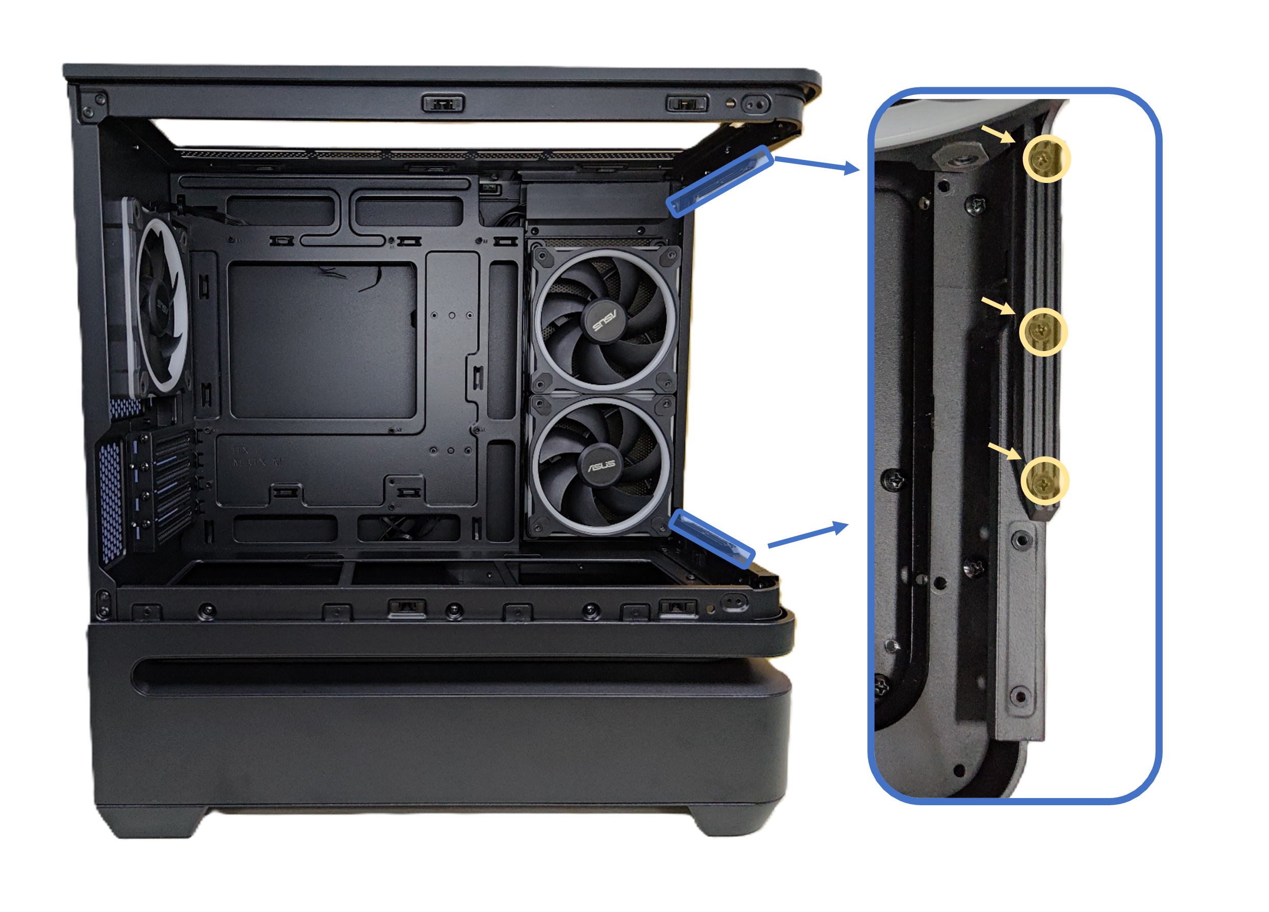
- Left Panel Track
Remove three securing screws for replacement.
Top Panel and Front IO
*Preparation: Before replacement, ensure all cable ties are removed and all connectors are disconnected from their headers.
1. Remove the Top Filter
2. Unscrew the four securing screws
3. Slightly slide the panel toward the back of the chassis.

4. Flip the top panel upside down
5. Unscrew the four securing screws of FIO module, detach the FIO module to top panel, pull the whole FIO module out along with cables.

Fan (For AP202 ARGB)
Rear Fan: Remove the four screws from the rear fan.
Side Fan: Remove the right door, then unfasten the four screws of the fan.

Lighting Module
*Preparation: Before replacing the module, ensure the ARGB cable is free of cable ties and the ARGB connector is disconnected from its header. Removing the side fan (if present) will provide more space for the removal process.
1. Turn the three thumbscrews on the bottom fan bracket counterclockwise to loosen them, then lift and remove the bracket.
2. Remove the two panel clips on the lower left side.

3. Unscrew the screw located on the front, and the three screws on the left side..
4. Unscrew the six screws securing the lighting module, then carefully pull the module and its cables out.

Feet
Tear the foot pad apart, then unscrew the securing screw to remove it.
*Note: The left front foot has a different shape than the other feet.

How to get the (Utility / Firmware)?
You can download the latest drivers, software, firmware and user manuals in the ASUS Download Center.
If you need more information about the ASUS Download Center, please refer this link.